Nixie bargraph clock - written by NiXijav on 2015-11-18

What happens when you combine an Arduino with something more vintage? Yes, a Nixie bargraph clock.
Recently I bought a couple of IN-9 Nixie bargraph tubes from a russian store, $1.5 each (quite cheap, huh?). These tubes are current driven, and they are fairly constant between 0 and 8 mA (Almost the end of the tube). Above that, sensitivity decreases rapidly. So, after keeping them in a shelve for some days because of not having any idea on what to do with them, I decided to make a clock.
A clock? - you might ask. Yeah, a clock. Neither analog nor digital. (Well, it is analog, but you know what I mean) Just the tubes displaying the time.
So, what do we need?
Obviously we're going to need the tubes and an Arduino (I'll be using a Pro Mini). Also, as the tubes run at 140v, an appropiate PSU is required. Mine boosts voltage from 8~32V to 100~390V, and it only costed ~$10. Also, I got a very nice wooden enclosure in a local store for just $3.
How to drive the tubes
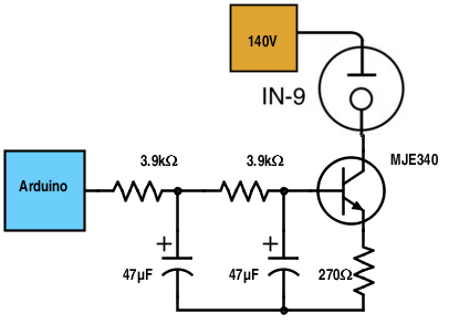
The main problem about driving each individual tube is the voltage itself. The Arduino is a 5 volt device, and 140v would very likely release the magic smoke. To avoid this, a high voltage transistor, like the MJE340, will be used. The first problem is now solved.
Another problem is the lack of a true analog output of the Arduino. Instead, it uses a PWM signal. The easiest solution is using a low pass filter, so the output PWM will be smoothed, much like an analog signal.
Take a look at the schematic of one of the tubes:

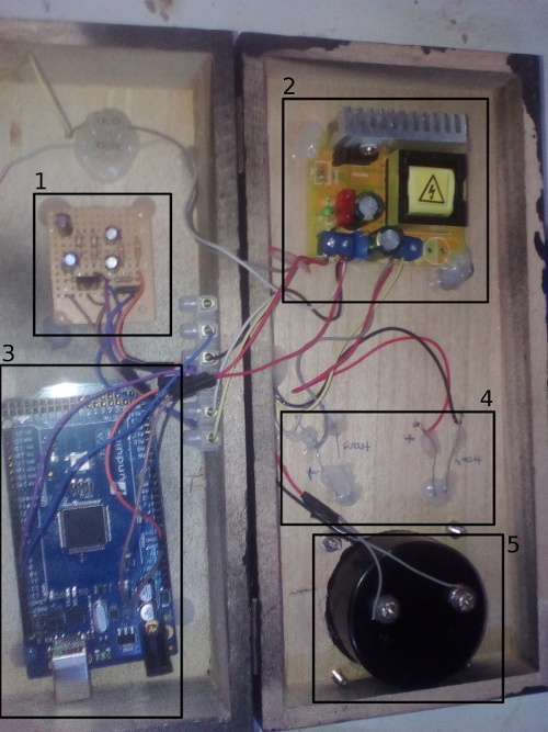
<irony>Now admire the internal magnificence of the clock!</irony>

Quick description of each part
- Low pass filters and transistors for each tube
- 140V Power supply
- Arduino Mega (Right now I'm using a Pro mini)
- Tube connections
- Decorative voltmeter
Tube height
One of the problems of the tubes is that each one is unique, so under the same voltage and current, two tubes can have slightly different heights. To adjust this, the resistor located on the emitter of each transistor should have the appropriate value. You could also put a potentiometer for easier adjustment.
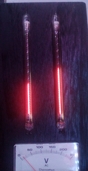
The final result!
So, how does this... strange clock look like? Here, take a look!

And there you have it! A steampunk vintage clock!

No comments yet
Leave a comment