Identity crisis, or how not to implement RFID - written by NiXijav on 2020-08-23

Some days ago, a place I usually frequent gave everyone an RFID access card. Security and convenience were the reasons given, but none of those was true.
TL;DR: Don't use Mifare UIDs to authenticate users, they are easily spoofed.Let's dive into a little investigation about the real security of this system. The first thing I did was scan the tag with my phone. Sure enough, with NFC Tools on Android, this is what appeared:
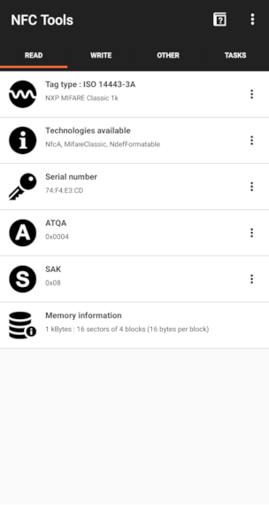
This is a Mifare Classic 1K Card, and it seems to be empty! Let's confirm this with another Android app, MIFARE Classic Tool. Reading a tag from this app is simple, Read Tag and then Start Mapping and Read Tag. And again, sure enough, the tag is empty. Could this mean they are using the card UID (serial number field in previous picture) to identify each user?
Pay special attention to the first line, the one in purple:
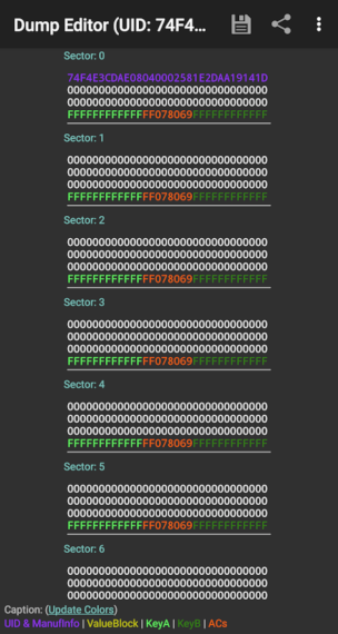
Also, as you may know, Mifare cards have different keys for different blocks. But as we just saw, security here is nonexistent, as all the keys are the default ones (FFFFFFFFFFFF, text in light and dark green). The conclusion is clear: they are using the card's unique ID as the user identifier. This is catastrophic because of three reasons:
- Not all users can access all places.
- With the default keys and only the UID as the identifier, card cloning is trivial.
- One can scan another user card to find other UIDs.
Time to clone our card and try it out. If you try to modify the UID on block 0 of your card (or the whole block for that matter), chances are it won't work. On genuine MiFare tags, block 0 is non-writable.
If you look closely on Chinese websites (can't give you any more clues or this would pose no challenge for you), you'll be able to find block 0 writable tags. These clones work identically as their original counterparts.
I haven't found an app yet able to write to these cards (they have a backdoor to enable block 0 writing), but an Arduino with the MFRC522 module and the RFID library will do. There's already an example sketch called ChangeUID, but for some reason, it didn't work for me. Using another example sketch as a reference (FixBrickedUID), I successfully wrote block 0. The code I used is available in this Gist.
I copied and wrote block 0 from the original card (purple text on the previous image) to the Chinese one. After verifying both cards were identical, it was time to test our clone.
And of course... it worked 🤦â€â™‚ï¸
P.S. Except for block 0, you can write to the rest of the original card. NFC Tools allows you to write different things like URLs and YouTube videos. If scanned with a smartphone, this content would pop up, and the door would still open normally. Quick idea: rickroll everyone (yes I tried, and yes it worked wonderfully 🕺).
Gauss Cannon - written by NiXijav on 2020-02-27

A futuristic sounding but technically simple device. Let's magnetically propel some scrap metal with this!
This project carries certain risks associated with the use of 230 VAC. These voltages are not a toy, and in the worst case it can lead to death. Take the necessary precautions and measures.
Although the title resembles some kind of futuristic or science fiction weapon, a Gauss cannon is actually a very simple device. It is also called ‘coil gun’. Its operation is based on the linear acceleration of a metallic and ferromagnetic projectile thanks to a magnetic field, due to high voltage and intensity provided by a capacitor. In other words, it is a solenoid.
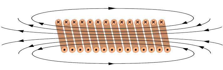 Magnetic field generated by a solenoid
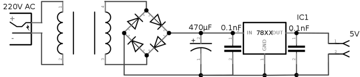
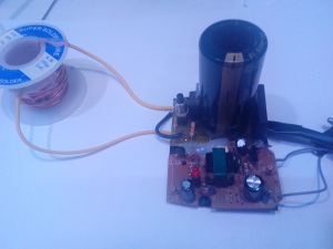
Here is my circuit:
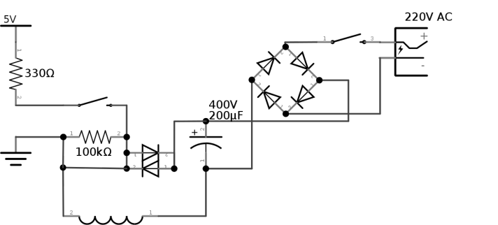
Broadly speaking, a diode rectifier is used to charge the capacitor, which converts AC to DC. It is important to note that 230V AC ≠230V DC. To calculate the voltage after rectification we can use this simple formula:
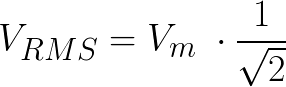
RMS means root mean square, or also quadratic mean. To avoid entering long descriptions, click here or here. Applying the formula is:
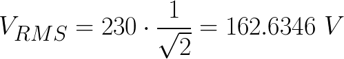
Finally, VRMS and VAC are added:

Therefore, we need a capacitor of that voltage or more. The chosen one is 400V. Another important thing to note is the use of a thyristor, instead of a normal switch to discharge the capacitor. This is because, in a very short period of time, the capacitor discharges a very large current, and normal pushbuttons or switches cannot withstand such a load. A thyristor can easily withstand 600V at 25A (as used in this circuit). They consist of 3 pins, one input, one output, and one drive. The latter can be triggered by 5V. In my case I used an old 5V charger, but you can also build a power source like this:
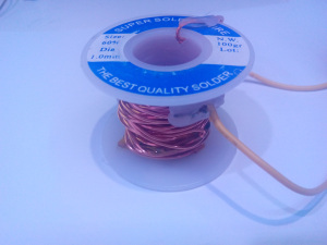
Finally, the coil is a simple copper wire wound in an empty tin roll. Ideally, we would have counted the number of turns and the length of the wire, in order to calculate the field strength, but I forgot and did not. In case of having these data, the field strength would be calculated with:
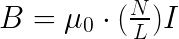
Being μ0 the magnetic permeability, which in the case of air would be 12.56 * 10-7; N the number of turns of the coil, L the length of the copper wire and finally I, the intensity of the current that is passing through the coil. To operate the cannon we will connect it to 230V. The charging time is very short, therefore it is better to put a switch. Once charged, when the second switch is activated, the one coming from the 5V source, the capacitor will discharge very quickly, generating the field in the coil, and also a short noise or zap. The position of the projectile inside the coil is important. The further from the center the projectile is, the faster it will exit and the more space it will travel.
Important note: Never operate the cannon while it is charging, or the diode rectifier will explode. (From own experience)
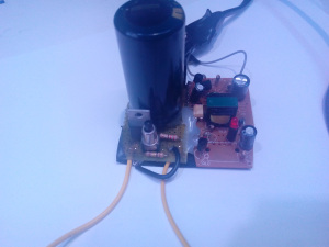
A good preventive method to avoid operating both at the same time is to put a triple state switch between charger and 5V source. Finishing now, some pictures of the already finished cannon:
Winter is coming - written by NiXijav on 2019-10-02

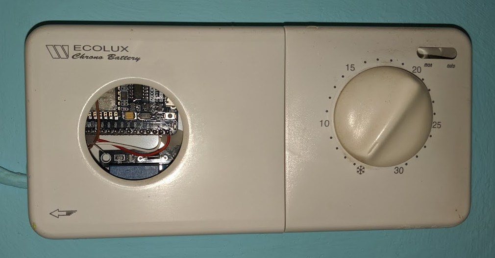
Upgrading an old, battery-powered thermostat
Winter is coming, and so does cold. It's time to turn on the heating and to enjoy a hot cuppa. But not without first automating and controlling with our phone our home's heating system.
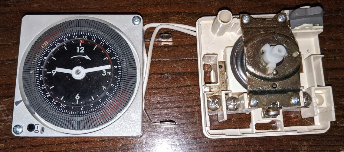
My current thermostat only allows me to program a 24h schedule, without regarding the temperature at all.
Wiring is as simple as joining the two wires found inside the thermostat; a relay will be perfect for this. I'll be using a NodeMCU as the controller as it has WiFi, and allows me to quickly set everything up before the tea goes cold.
Choose any digital pin of the NodeMCU, and connect the relay to it. Then, connect the heating cables to the relay. It should look like this:
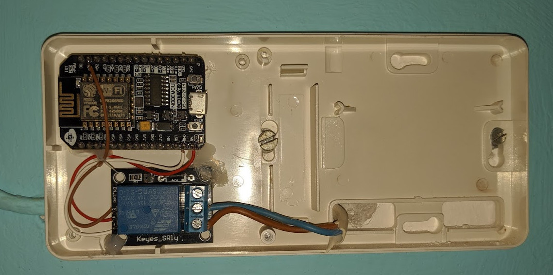
After closing the case...
It's time to flash the NodeMCU firmware. The code is available here https://github.com/ResonantWave/heater-bot/tree/master/heat_nodemcu. Don't forget to set your WiFi SSID and password!
Now it's time to control it. I'll be using a Telegram bot, that will allow us to turn on or off at any moment the heating. We will also be able to set a basic schedule. Files are available here https://github.com/ResonantWave/heater-bot/tree/master/heat_telegrambot. To spin up the Telegram bot, you'll need an API Key from the Botfather. Also, don't forget to configure the NodeMCU Ip address.
When finished, the bot will be able to control your heating. No more cold cuppas ensured!
There's still a lot of work to be done on the bot, allowing to individually schedule each day or with recurring times. Another nifty improvement would be a temperature sensor, to stop heating when necessary.
If you are having any trouble using this bot drop me a line in the comments and we'll solve it!
