Upgrading a mouse with a 555 timer - written by NiXijav on 2015-12-20
Cookie Clicker is fun, but it is necessary to click a lot so my finger gets tired and my mouse broken. So, why not use a 555 timer to automate clicks?
I've been playing Cookie Clicker for the past hour. It is very addicting, but it advances quite slow. It is also necessary to click a lot, so mi finger gets tired and my mouse, destroyed. So, why not use a simple 555 timer to perform automatic clicks? Let's go!
The 555 timer is one of the most sold and used ICs in the world, due to its low cost, ease of use and application diversity, that ranges from a delayed switch to an oscilloscope. Here's a datasheet for the chip.
The timer has several working modes, monostable, bistable and astable. The one we need is the astable one.
In this mode, the chip will provide a constant pulse sequence specified by us. This is what we want to achieve, fast and constant pulses, just as if we were clicking the mouse.
Here's the circuit:
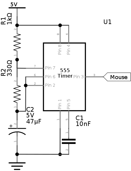
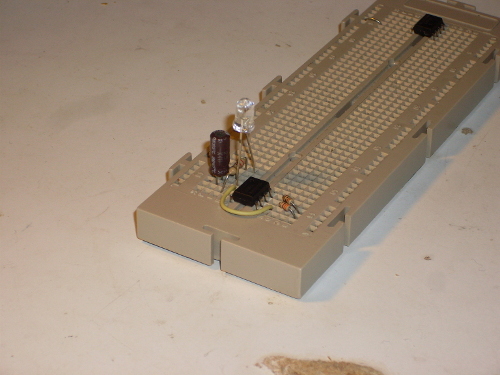
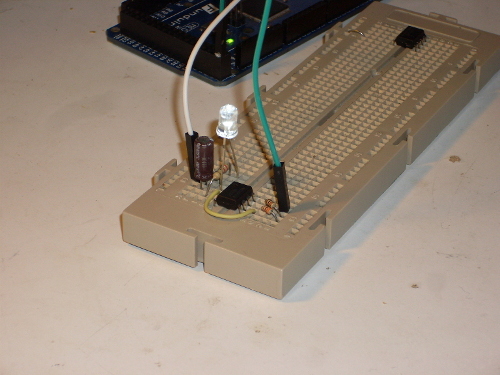
Quickly making this circuit on a breadboard, and connecting the output to an LED (instead of the mouse) we get this:
What frequency is being achieved with this circuit?
![]()
Wow! 18.5 Hz! Quite impressive, isn't it? That's a huge improvement over the manual click. Oh, and don't forget the period:
![]()
Furthermore, we can calculate charge and discharge times:
![]()
![]()
After all this calculations, and checking that the circuit is working properly, let's solder everything. In short, you must first check that there is room inside the mouse to house the circuit. It will be powered by the USB bus power itself. The following photos describe this process:
This mouse is very easy to open. Just 4 screws on the base and the top just pops off.
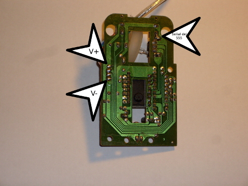
Next, remove the board from the case and analyze where cables should be soldered (V+, V- and signal).
V+ and V- come directly from the USB, and the signal wire should be soldered to the push button contact. This way, the button will preserve its original behaviour, but when we press the new added button, the signal will be sent through the original, performing the clicks. After connecting everything, we proceed to the reassembly.
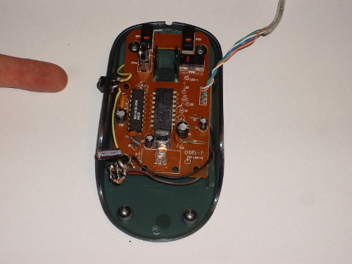
Be careful when accommodating the cables! Oh, and, my finger is pointing to the new button. After everything is again in place, my mouse looks like this:
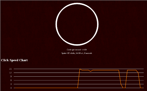
And last, but not least, quick check on cookie.riimu.net/speed
Nixie bargraph clock - written by NiXijav on 2015-11-18

What happens when you combine an Arduino with something more vintage? Yes, a Nixie bargraph clock.
Recently I bought a couple of IN-9 Nixie bargraph tubes from a russian store, $1.5 each (quite cheap, huh?). These tubes are current driven, and they are fairly constant between 0 and 8 mA (Almost the end of the tube). Above that, sensitivity decreases rapidly. So, after keeping them in a shelve for some days because of not having any idea on what to do with them, I decided to make a clock.
A clock? - you might ask. Yeah, a clock. Neither analog nor digital. (Well, it is analog, but you know what I mean) Just the tubes displaying the time.
So, what do we need?
Obviously we're going to need the tubes and an Arduino (I'll be using a Pro Mini). Also, as the tubes run at 140v, an appropiate PSU is required. Mine boosts voltage from 8~32V to 100~390V, and it only costed ~$10. Also, I got a very nice wooden enclosure in a local store for just $3.
How to drive the tubes
The main problem about driving each individual tube is the voltage itself. The Arduino is a 5 volt device, and 140v would very likely release the magic smoke. To avoid this, a high voltage transistor, like the MJE340, will be used. The first problem is now solved.
Another problem is the lack of a true analog output of the Arduino. Instead, it uses a PWM signal. The easiest solution is using a low pass filter, so the output PWM will be smoothed, much like an analog signal.
Take a look at the schematic of one of the tubes:

<irony>Now admire the internal magnificence of the clock!</irony>
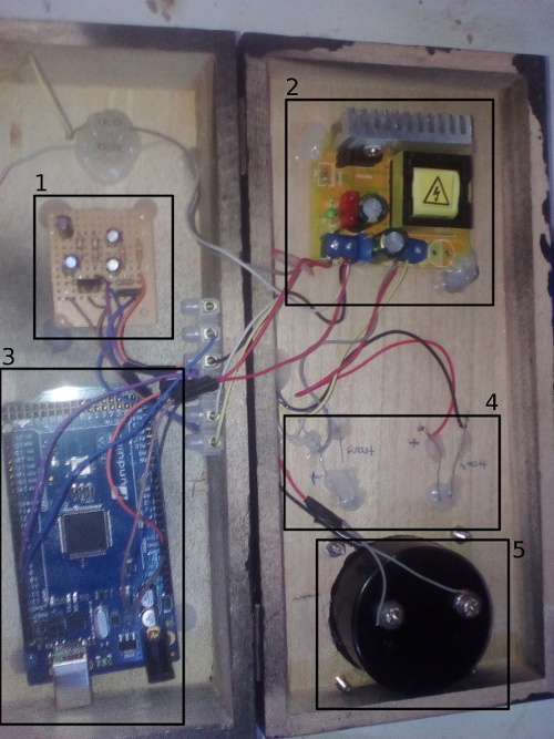
Quick description of each part
- Low pass filters and transistors for each tube
- 140V Power supply
- Arduino Mega (Right now I'm using a Pro mini)
- Tube connections
- Decorative voltmeter
Tube height
One of the problems of the tubes is that each one is unique, so under the same voltage and current, two tubes can have slightly different heights. To adjust this, the resistor located on the emitter of each transistor should have the appropriate value. You could also put a potentiometer for easier adjustment.
The final result!
So, how does this... strange clock look like? Here, take a look!

And there you have it! A steampunk vintage clock!
BabbageBot - written by NiXijav on 2015-10-15

BabbageBot is a Python bot for Slack. Modular, easy to use and fun.
BabbageBot is a Python made bot for Slack, the communication tool for teams. The bot provides easy to add and easy to modify commands that can greatly expand the experience of chatting.
It was made with the intention of being modular, enabling anyone that wants to modify it to do the changes very easily. The structure of the bot is:
├── LICENSE
├── main.py
├── modules
│ ├── btc.py
│ ├── calc.py
│ ├── help.py
│ ├── __init__.py
│ ├── iss.py
│ ├── list.py
│ ├── ping.py
│ ├── rand.py
│ ├── translate.py
│ ├── weather.py
│ └── wiki.py
└── README.rst
The main.py contains the main methods for connecting to the Slack API through a Websocket. An API key is required. This file also loads the modules/list.py. List.py enumerates all the available modules (aka commands), and main.py uses this list as the message filter. When a string is detected to be in the list, this message gets delivered to the appropriate module. Result is then returned from the specific module and sent back to Slack.
The modules folder, as already said, contains all the modules that can be used by the bot. Each command should have its own file. Not required, but recommended.
For example, calc.py computes any kind of mathematical expression by sending the data to a server and then retrieving the result. Modules like the weather one require an API key. (In this case, from Openweathermap)
Adding a command is pretty simple. Create a .py file with any name in the modules/ folder. Then create the 'execute' function, with an string as a parameter (even if you don't use it). For example, I'll use the file 'wiki.py' (Fetches the Wikipedia). Inside the execute function I have all the necessary code to fetch the relevant Wikipedia article based on the given arguments.
After the code is properly written and working, an entry should be added in modules/list.py. First, importing it (eg, 'import wiki'); and then adding the entry itself in 'commandModules'. In this case I would add ''wiki': wiki'. The first 'wiki' is the keyword the bot will be listening for executing the command specified on the second half, 'wiki'. You could also have ''potato': wiki', and then sending to the bot 'potato Trees' would return the Wikipedia article about trees.
BabbageBot is distributed under the GNU Affero GPL v3 license.
For more information on installing, modifying and redistributing, please visit this GitHub repository: BabbageBot
